Tech Talk
TECHNICAL UPDATE – “FIRST UNDERSTAND THE PROBLEM”
Here at Thompson Couplings we strive to design and deliver to you the best available product for your particular driveline requirements.
We don’t just sell the standard off-the-shelf coupling BUT will work with you (if needed) as the end user to understand the problems with your current situation and deliver a technical solution.
Based on our many years’ experience in driveline and machinery systems we understand that often it may not be obvious the cause of a systems vibration or noise or poor life etc. From lessons learned it is not wise to dive in and think it must be the coupling that is the culprit all to find the problem may still be there after the coupling has been replaced.
Instead take a look at the entire driveline and connected machinery and using some simple tools try and pinpoint where the originator maybe. In future articles I will elaborate more but simple checks such as:
- Worn pump bearings will give signs of vibration even though the couplings maybe fine
- Sloppy Vee belts or poor tension will give false readings in vibration
- Loose motor mounts or pump supports will likewise give high vibration readings and make alignment impossible when using other specific types of couplings.
- Etc.
The simple tools I mention include your sight, sounds and feel to safely identify possible sources of trouble first before bringing in the technical equipment. Use a screwdriver to your ear to listen to worn bearings, feel with your hand indications of hot spots in the shaft couplings or other components. REMEMBER though safety first when you are close to rotating machinery!
Next time we’ll discuss case histories to show how this all can be applied.
TECHNICAL UPDATE – “PROBLEM SOLVING EXPERIENCES”
At other times a refit project may take place whereby a new prime mover (motor, engine etc) forcing the established axis alignment to be changed and no suitable coupling can be found to work.
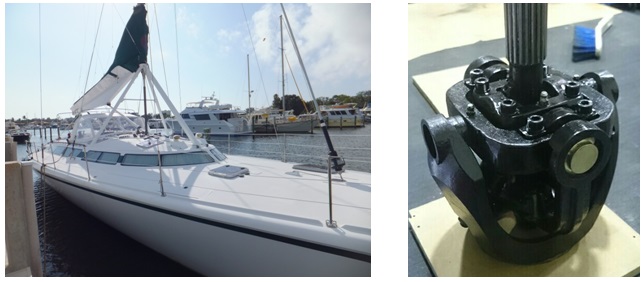
A few years ago our engineers were presented with a sailing boat enquiry that had recently undergone a new engine refit. This new diesel engine had a shaft axis significantly higher than the previous engine hence the alignment with the existing fixed propeller shaft was compromised. If the traditional universal joints were to be installed the new angles were no longer compatible to provide constant velocity to the final drive.
Working closely with the boat owner and using his design drawings our team were able to calculate and offer him our unique Thompson Constant Velocity Joint (TCVJ 5B-15) to link the new engine and existing propeller shaft. The true constant velocity of the coupling provides near vibration free motion for the vessel and has since proved very reliable.
In his own words;
I can honestly say that your CV joint inexpensively solved a major problem during a refit of Route 66 done in 2011. We had decided to replace a finicky and high maintenance “saildrive” with a conventional propellor shaft and coupling. However, because of our engine placement and lifting keel we needed a true CV joint that could handle over 100 hp with an 8.5 degree change in shaft angle. Your brilliant joint allowed us to do this. The joint has been trouble free and functioning beautifully with minimal maintenance over several thousands of miles during this interval and I would certainly do it the same way over again and not hesitate to recommend it as a CV joint for any application given my experience.
TECHNICAL UPDATE – “Torque, Power and Speed Part 1”
Torque (Nm) = 9550 x Power (kW) / Speed (rpm).
This formula defines the linear relationship that one may see with a certain AC electric motor with different pole configurations, such as 2, 4, 6 or 8 pole that modify the synchronous speed in line with the pole number. Thus while the line frequency of say 50Hz (Australia) produces a theoretical synchronous speed of 3000 rpm for a 2 pole motor that same sized motor with a 4 pole configuration would sync at half that speed or 1500 rpm and its torque would be doubled (as per the linear formula above). The same relationship occurs in USA (60Hz) but the respective speeds become (3600 and 1800 rpm)
Where I have seen folk come unstuck is when motors are controlled by a Variable Speed Drive (VSD or VFD) and recording the final output speed BUT applying that same formula. It is erroneous to double the torque in this situation if the speed is halved. The principle of the VSD is to REDUCE the power as the Speed is reduced and hence the Torque effectively remains CONSTANT.
A simple chart shows this as follows:
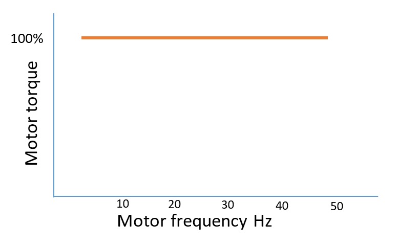
So when selecting a suitable coupling based on the motor torque it is vital to understand how the system is controlled (VSD, DOL etc) and operated.
Next time we will discuss other types of power sources.
David Farrell – B.E. Mech (hons)J
(David Farrell is Chief Engineer for Thompson Couplings – designers and manufacturers of The Thompson Constant Velocity Joint. David has more than 30 years as a professional mechanical engineer involved in a wide range of mechanical engineering designs and maintenance projects. He was one of the key founders of Thompson Couplings Ltd since 2001 and continues to design the range of TC products as well as support the engineering community with specific applications for power transmission and shaft couplings.) www.thompsoncouplings.com
TECHNICAL UPDATE – “Torque, Power and Speed Part 2”
In a previous update we discussed how the fundamentals of power, torque and speed are related by the equation Torque= 9550 x Power/rpm
This linear relationship only holds true while ever power is constant, such as in a single or multi-phase electric motor running at synchronous speed. It also holds true when a fixed speed reduction device is used such as a gearbox or vee belt drive where the torque can be easily evaluated.
But what happens when the power is not constant across a prime movers speed range?
Consider for example a diesel engine of either single or multi cylinder configuration. An internal combustion engine such as this will generate its peak power at a certain rpm point. Either side of that point the power, and also torque, will diminish. One cannot expect the same torque relationship as previously mentioned to be applied to such a machine.
So when trying to size a suitable shaft coupling for a diesel drive to, say a fire fighting pump, what torque value does one choose for its size?
The solution we adopt is to study the specific performance curve particular to the engine in question. Engine manufacturers publish their own power, speed and fuel consumption curves for each model. By studying these curves one can select the point of operation where peak torque occurs, which is not the same as the peak power point. For instance Volvo Penta publish the following curves for their D12 range of marine inboard diesel engines:
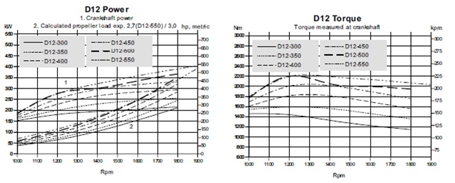
While peak power is developed at crank speed of 1800 rpm or more the peak torque is found to occur at around 1200-1300 rpm. Trying to apply the linear equation for power and torque would give an erroneous answer in the engine torque at peak power. Thus to size an appropriate coupling based on its torque capacity one must start with the engine peak torque from its specific curve.
The same logic applies to other non-linear power sources such as gas turbines or even wind power generators where understanding the whole system is the key to successfully sizing a suitable shaft coupling.
At Thompson Couplings Ltd we have developed a sophisticated method for calculating the effects of various power sources speeds and torque patterns to enable us to design the correct coupling to suit individual applications.
David Farrell – B.E. Mech (hons)J
(David Farrell is Chief Engineer for Thompson Couplings – designers and manufacturers of The Thompson Constant Velocity Joint. David has more than 30 years as a professional mechanical engineer involved in a wide range of mechanical engineering designs and maintenance projects. He was one of the key founders of Thompson Couplings Ltd since 2001 and continues to design the range of TC products as well as support the engineering community with specific applications for power transmission and shaft couplings.) www.thompsoncouplings.com
TECHNICAL UPDATE – “Understanding Shaft Alignment”
The subject of shaft alignment has been recorded in great depth by others over the decades and it is not for me to regurgitate the entire science (some may say a black art!)
What is laser alignment?
Laser alignment is the alignment of two shafts connected to 2 pieces of equipment within a tolerance, so that the connected equipment won’t suffer from Energy over load, pull more power from the Electric Motor, or effect premature failure of ancillary products such as, Bearings, seals, V Belts, Pulleys, Couplings or gearbox failure, pump failure, fan failure for example on rotating equipment.
Why laser align?
In recent times laser alignment has become an industry standard for engineers and maintenance staff to improve the reliability of their plant and equipment. This is because misalignment between rotating shafts causes undue vibration, noise and wear for such items as shaft seals and bearings leading to significant reduction in their useful life. Studies also show that significant energy losses can occur when particular types of shaft couplings are misaligned due to the added side loads on the connected shafts.
Old Methods of alignment.
Old methods of alignment would use things like, piano wire, ruler, line of sight or dial indicators.
Modern methods of alignment and what they are:
While the advent of modern technology has enabled users to “plug and play” their alignment equipment (laser etc) to achieve a simple and quick result it is incumbent on us as technicians to understand the fundamentals of what is required and not just rely on a digital readout – sometimes erroneously.
2 methods of Alignment.
I like to categorise the requirement for shaft alignment into two distinct areas:
- Requirement for STATIC Alignment – or while the machine is stationary
- Requirement for DYNAMIC Alignment – that is when things start rotating
Clearly the majority of alignment methods can only focus on the first point – machines can only be aligned when stationary.
The importance of alignment and why.
It is here that every attempt is made to ensure coaxial alignment is achieved between the drive and driven shaft. This is usually done in both planes in line with the rotation axis with some degree of tolerance. The precision for alignment varies for the type of coupling involved however since many couplings have some type of flexural element involved any deviation from “perfect” will result in some degree of side loading being induced to the shafts proportional to amount of tolerance offset. The detrimental effects of misalignment (no matter how small) will be seen over time in component wear (seals, bearings etc), additional power consumption and eventual failure.
Why Coupling Manufacturers insist on tight tolerance values.
Most coupling manufacturers insist on such tight tolerance values to be adhered to for their product installation. They therefore take great effort (and expense) to align the shafts by either shimming motor or pump feet or making other adjustments to obtain coaxial alignment as far as practical.
Load cycles, flex or distort.
Great but now what happens when the machinery is energised, and various loading cycles undertaken? This is where the requirement for Dynamic Alignment is most important. As we know things flex or distort under dynamic actions such as:
- initial torque energisation of a motor in a DOL configuration
- fluctuations in torque when a pump is loaded or unloaded
- torque changes when the gearbox of a rolling mill is loaded or unloaded with product
- thermal expansion from connected pipework to machines such as boiler feed pumps or turbines
- etc
Other significant factors can also cause things to go out of alignment – as simple as loose mounting bolts, flexible machine support bases and even corroded foundations all giving rise to the term “soft foot”. Almost no amount of STATIC alignment can solve the issue of soft foot as the connected machinery will flex the coupling to suit the loaded conditions.
Excessive loads
Generally, it is hoped that these dynamic limits are of a low enough order that the coupling tolerance can accommodate the resulting flexure. BUT as mentioned the resulting flexure will place a burden in the form of side loading onto the connected shafts and create extra wear, consume additional power and cause premature failure of the drivetrain.
While most other coupling designers need to balance the flexural requirement within tight tolerances it still stands that precision alignment can be rarely achieved in an economical way when dynamics are present.
Is Laser alignment dead?
As technology moves so fast in other industries some industries move slower, the Mechanical coupling other than materials has not moved on much in the last 100 years, this type of technology seem to have not changed with the times and we move ever faster is their now an advancement in mechanical couplings that will NOT require laser alignment a coupling that can handle side loads, vibration, accept lager misalignment without effecting the connected equipment, it will be energy efficient even when misaligned and installation will be in the minutes not hours, if you read the next part there is a company who has made one of the biggest advancements in coupling technology in the last 300 years, that have solved all of the issues spoken about in this article, so the questions you may ask yourself, IS LASER ALIGMENT DEAD? That solely depends on if you as a engineer, designer engineer are will to embrace this new tech and move forward into a new of technology before your competitors do.
Biggest leap in coupling technology in the last 300 years.
The Thompson TCAE range of products has therefore been designed to eliminate the need for precision alignment in the first place,Furthermore its self-adjusting features permit dynamic forces such as thermal expansion and soft foot to be catered for without imposing damaging side loads on the shafts.
The unique double hinged internal mechanism transmits torque at constant velocity and reduces imposed vibrations from rigidly mounted machines. With its wide range of movement (radially +/- 5 degrees and axially up to +/- 15 mm) it also provides effortless installation with minimal downtime. Tests have also been conducted to prove the energy saving potential of the TCAE compared to other flexural element couplings when various degrees of misalignment are created. The result is the TCAE does provide a positive cost/benefit return for most plant, with quicker installation, energy saving, reduced repairs on connected equipment, able to handle vibration and less down time for plant and equipment, the benefits are massive for your plant operation production run time with minimum down time.
David Farrell – B.E. Mech (hons)J
(David Farrell is Chief Engineer for Thompson Couplings – designers and manufacturers of The Thompson Constant Velocity Joint. David has more than 30 years as a professional mechanical engineer involved in a wide range of mechanical engineering designs and maintenance projects. He was one of the key founders of Thompson Couplings Ltd since 2001 and continues to design the range of TC products as well as support the engineering community with specific applications for power transmission and shaft couplings.) www.thompsoncouplings.com

TECHNICAL UPDATE – “Shaft Alignment”
For over 50 years now our manufacturing industries have followed world’s best practices in equipment maintenance strategiesfrom and rightly so. These programs invariably have followed some form of continuous improvement philosophy (with various acronyms and terms) all to improve machine reliabilityand plant uptime.
In my early days it was TPM whereby regular work order routines were religiously printed off on a regular basis to perform planned maintenance on all equipment (over time) whether it needed it or not. This progressed to condition based monitoring to actively monitor the health of equipment and step in at the last minute to repair/overhaul or replace before failure occurs. While this process is still in use statistical probability techniques have been introduced for risk based maintenance to eke out resources based on risk vs return.
While these programs are valuable to companies they often only address the existing plant equipment and, as a machine designer, rarely do they complete the circle to integrate new equipment being introduced. I have often seen new plant being installed with the same inherent problems being experienced by existing plants but as long as the new plant has a condition maintenance routine in place it’s covered! Sometimes we seem to be blindly following existing paradigms without challenging why or is there a better way.
Take something as simple as motor to pump shaft alignment. We are conditioned now to accept how precious accurate shaft alignment is only because IT IS BASED ON THE TYPE OF COUPLING USED. Our maintenance orders and routines are full of regular Laser Alignment procedures to ensure the utmost precision is taken to ensure long reliable life. While this is no unfair reflection on the importance of Laser Alignment the real culprit is the lack of development in modern couplings that often require this sort of accurate alignment to be integrated.
In a previous article we discussed the different types of shaft alignment – Static and Dynamic. Whilst all forms of couplings may be accurately aligned with their respective connected shafts in a Static condition (Laser or other means) things can drastically change when dynamics take over. These dynamic effects will undermine the initial static setup if they are severe enough to extend beyond the tolerance range of the coupling.
The TCAE couplingwas developed by Thompson Couplings to suit the growing need of maintenance technicians to counter the demands of certain dynamic situations and stop the premature failure of existing couplings and their connected devices. This TCAE coupling, that has real alignment Eliminating capabilities, does exactly what it must,by automatically accommodating to the dynamic effects of shaft misalignment. It has a full range of freedom from radial to axial compensation with limits far in excess of standard couplings and beyond what industry actually require.
Having an angular alignment freedom of +/- 5 degrees with little resistance it exceeds limits for most connected applications. The internal double hinge arrangement of the coupling also permits all manners of misalignment including axial, parallel and combination offset in all planes.
This unique feature allows the TCAE coupling to be simply installed to suit the existing situation of both motor and driven device with no need for precision alignment. As is often the case when a pump is overhauled and brought back into service standard procedure involves laser aligning the coupling first. This adds extra time and cost to the situation to which the dynamic effects may afterwards negate the precision alignment in the first place.
By comparison the TCAE coupling is a set and forget option that engineers and maintenance personnel are using more and more to improve downtime and equipment reliability.
David Farrell – B.E. Mech (hons)J
(David Farrell is Chief Engineer for Thompson Couplings – designers and manufacturers of The Thompson Constant Velocity Joint. David has more than 30 years as a professional mechanical engineer involved in a wide range of mechanical engineering designs and maintenance projects. He was one of the key founders of Thompson Couplings Ltd since 2001 and continues to design the range of TC products as well as support the engineering community with specific applications for power transmission and shaft couplings.)www.thompsoncouplings.com
TECHNICAL UPDATE – “Driveline Vibration”
In the years since we first developed the Thompson Coupling TCVJ® the most successful application has been for stern drives in various marine vessels. There are 3significant reasons for this success:
- Ability to adapt to unequal drive angles between engine/gearbox and stern prop shaft- often as a result of engine refits
- Demonstrated quality product to reduce driveline vibrations for marine propeller shafts
- Cost affordability for marine users
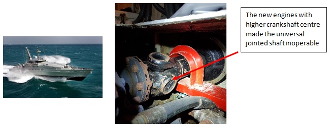
Often when a vessel undergoes an engine refit the new power source is invariably different from the original unit. As such the crankshaft height entre is different to previous and hence the original driveshaft (normally a universal jointed or cardan shaft) is unusable without significant changes.
The fundamental requirement for any universal jointed (UJ) shaft is to have equal angles between the driver/ shaft and driven/shaft Thus is if the engine has a crankshaft angle of 5 degrees down then the driven stern shaft must also have the same angle (up or down – doesn’t matter). This is because the non-constant velocity nature of the intermediate shaft after the first UJ must be phased at 90 degrees by the second UJ in order to provide constant velocity at the final drive. This is why the 2 axes are parallel.

In the special case of marine drives the stern shaft is often slanted down (say 8 degrees) and therefore the engine gearbox has a similar angled output. However what some marine users have down is to use a standard horizontal output engine gearbox and , in combination with the TCVJ, used unequal angles to provide true constant velocity for the propeller. The unique feature of the TCVJ is its ability to transfer torque at an angle, with no sliding surfaces, at true constant velocity.
One customer had rebuilt his luxury sailing yacht with a new improved diesel engine. However since the mating angles were dissimilar he had to find another drive coupling arrangement. Working with the Thompson Coupling engineers he fitted the TCVJ 5B-15 coupling and shaft and has achieved over 10 years continuous successful operation. The resulting drive is virtually vibration free, smooth and reliable.
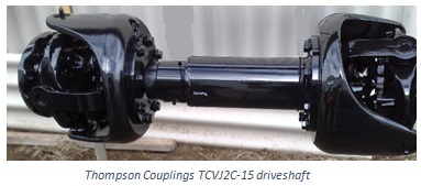
In a similar situation a well renowned service provider in the UK have fitted the larger TCVJ 2C-15 Thompson Coupling to one of the MOD navy tug boats. The vessel was recently fitted with new 500 HP diesel engines that also created dissimilar shaft angles with the stern drive shaft.
After running the new drives since August 2019 the client has reported back excellent vibration free running and reliable operation.
David Farrell – B.E. Mech (hons)J
(David Farrell is Chief Engineer for Thompson Couplings – designers and manufacturers of The Thompson Constant Velocity Joint. David has more than 30 years as a professional mechanical engineer involved in a wide range of mechanical engineering designs and maintenance projects. He was one of the key founders of Thompson Couplings Ltd since 2001 and continues to design the range of TC products as well as support the engineering community with specific applications for power transmission and shaft couplings.)www.thompsoncouplings.com
TECHNICAL UPDATE – “Energy Savings”
One of the key features of the TCAE-R series couplings is its unique double hinged mechanism that induces minimal radial load onto the connected shafts. In contrast flexible couplings of the elastomeric type produce significant power losses when the shafts are not perfectly aligned. Our company produced a series of experiments to quantify this fact.
A 0.75kW electric motor was coupled to a generator mounted on a sliding frame. An electric actuator controlled the relative position of the 2 shaft centrelines to produce an adjustable parallel offset condition.
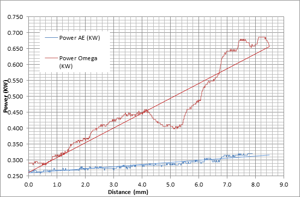
A Thompson TCAE-2-R coupling and a standard Rex Omega (30) elastomeric coupling were subjected to a series of tests by recording the power consumption of the driveline when the shaft centrelines were offset from 0 to 8mm. Normally the Rex Omega coupling would not be subjected to such a high amount of flex however at the maximum recommended offset of 1/8” (3mm) allowed the energy reduction was very apparent.
In contrast the TCAE coupling maintained a slight rise in power consumption over the large offset distance due to small losses within the coupling
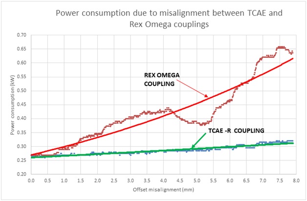
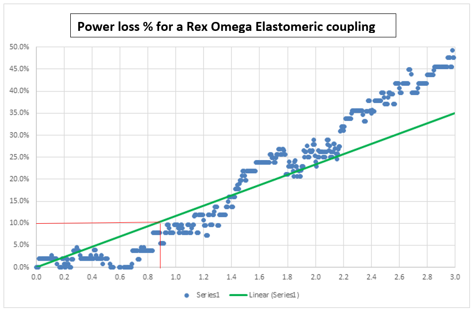
When the results are converted to an energy loss percentage within the normal range of allowable alignment for the Omega coupling we can see quite significant differences. Moreover at a relatively minimal offset of 0.9mm (0.035”) for this type of coupling losses of 10% energy can be observed.
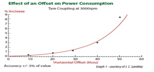
The results are not unique and have been previously replicated by others including JC Lambley formerly of ICI Chemicals as shown below:
The TCAE – R coupling provides significant cost advantages in terms of energy savings and total cost of ownership through reduced power consumption, elimination of shaft alignments services, reduced wear on connected bearings and seals etc.
David Farrell – B.E. Mech (hons)J
(David Farrell is Chief Engineer for Thompson Couplings – designers and manufacturers of The Thompson Constant Velocity Joint. David has more than 30 years as a professional mechanical engineer involved in a wide range of mechanical engineering designs and maintenance projects. He was one of the key founders of Thompson Couplings Ltd since 2001 and continues to design the range of TC products as well as support the engineering community with specific applications for power transmission and shaft couplings.)www.thompsoncouplings.com
TECHNICAL UPDATE – “Cost Effective Maintenance”
In a recent post we illustrated the potential energy savings that can be made over alternative types of motor shaft couplings using the Thompson TCAE-R coupling.
As a former maintenance engineer for a large manufacturing group the continual cost pressures to perform under budget and maintain the highest plant runtime was always in the forefront of one’s daily duty. To develop the latest maintenance system using such terms as Preventative Maintenance, Predictive Maintenance, and Proactive Maintenance for our rotating machinery (pumps, rolling lines, gear trains, presses etc.) demanded a good understanding of the components reliability and the associated test and measure tools.
As many engineer has already said the reliability of a good pump or roller drive is only as good as the shaft coupling that drives it. Unless specified directly at the outset many OEM machines are often purchased unfortunately with the cheapest motor shaft coupling that have untimely let the system down due to failure or else burdened with lengthy maintenance schedules to keep the alignment in its critical state. Not only the expense but the time required to perform accurate laser alignment on such rotating machines costs the plant enormously in lost production that is extended to the many, many instances of like machines across most large plants.
The effective management of such as simple thing as a shaft coupling can be achieved with self-aligning couplings such as the TCAE-R by Thompson Couplings Ltd.
Compared to other types the TCAE-R coupling offers a fully sealed alignment eliminator device that can be removed from the high intense PM schedule of a plant. The TCAE-R coupling is akin to a “set and forget” device that remains fully sealed with no alignment requirements to be regularly checked. Not be misled the TCAE-R coupling will require a quick visual and audible observation as part of a much longer schedule to check for such events as damage from extraneous sources for example
Furthermore it’s “out of sight – out of mind” abilities lend themselves to applications that are often in remote and/or inaccessible places. Such examples include remote water feed pumps in minesites or pumps situated in hazardous areas that may require difficult and elaborate entry permits to access that would ordinarily require routine coupling alignment activities to be performed. In these instances the “set and forget” nature of the TCAE-R frees up the resources of the maintenance team for other more demanding duties.
David Farrell – B.E. Mech (hons)J
(David Farrell is Chief Engineer for Thompson Couplings – designers and manufacturers of The Thompson Constant Velocity Joint. David has more than 30 years as a professional mechanical engineer involved in a wide range of mechanical engineering designs and maintenance projects. He was one of the key founders of Thompson Couplings Ltd since 2001 and continues to design the range of TC products as well as support the engineering community with specific applications for power transmission and shaft couplings.)www.thompsoncouplings.com
TECHNICAL UPDATE – “Thompson TCVJ® Coupling to Marine Driveshafts”
One market realising the benefits of the Thompson Constant Velocity Joint TCVJ® is the marine industry.
Specifically the integration of the TCVJ® to the powertrain that permits large angles of misalignment to be achieved is proving beneficial to many types of marine vessels.
Traditional types of powertrain shaft couplings – such as universal joints – have great limitations when the connecting angle from engine/gearbox to propeller shaft is moderately large (typically greater than 3 degrees)as significant shaft vibrations often occur. Additonally,with the flexible nature of the hull, shaft coupling misalignment creates further disturbances and energy losses in the powertrain from unwanted shaft side loads.
One recent application has seen the installation of the TCVJ®constant velocity shaft coupling for the main propulsion in a naval patrol boat. This vessel was recently refitted with two new 500HP engines. Since the newer engines had a crankshaft centreline significantly higher than the previous types created a new uneven shaft angle. As such a traditional universal joint shaft solution if fitted would lead to significant shaft vibrations when operating at normal engine speeds.
The boat builder turned to Thompson Couplings Ltd to develop a solution that would permit the new engines to be installed with minimal changes to the rest of the driveline.
The Thompson Couplings model TCVJ-2C-15 with nominal articulation angle up to 15 degrees was fitted with appropriate adaptor flanges to suit the new engine flywheel and gearbox flange. Once installed the resultant shaft angles measured 5 degrees at the engine flywheel and 1 degree at the gearbox. Since the TCVJ® operates at constant velocity at different angles (unlike a universal joint) the resulting vibration spectrum was smooth and well below permissible levels.
The resulting benefits of the Thompson TCVJ® driveshaft to the boat builder included:
- Easy retro fitment of new modern engines in older craft without the need to maintain accurate alignmentof existing propeller shafts
- Energy savings through the use of highly efficient coupling technology minimising shaft side loads
- Proven reduction in vibration levels due to pure constant velocity shaft rotation
- Resultant low noise signature of the craft from low vibration of the driveline- especially useful in military applications.
David Farrell – B.E. Mech (hons)J
(David Farrell is Chief Engineer for Thompson Couplings – designers and manufacturers of The Thompson Constant Velocity Joint. David has more than 30 years as a professional mechanical engineer involved in a wide range of mechanical engineering designs and maintenance projects. He was one of the key founders of Thompson Couplings Ltd since 2001 and continues to design the range of TC products as well as support the engineering community with specific applications for power transmission and shaft couplings.)www.thompsoncouplings.com
TECHNICAL UPDATE – “Shaft Alignment savings explained with TCAE ™ ”
Shaft Alignment savings explained with TCAE ™ shaft couplings.
As many engineers know the reliability of a good pump, geartrain, or any other powertrain is only as good as the shaft coupling that drives it. Unless specified directly at the outset, many OEM machines are often purchased, unfortunately, with the most basic motor shaft coupling that have untimely let the system down due to failure or else burdened with lengthy maintenance schedules to keep the alignment in its critical state. Not only the expense, but the time required to perform accurate shaft alignment on rotating machines costs the plant enormously in lost production from downtime.
While the advent of modern laser alignment technology has enabled users to “plug and play” their instruments to achieve a quick result, just relying on a digital readout is a mistake as errors in reading sometimes occurs.The requirement for shaft alignment can be categorised into two distinct areas:
- Requirement for STATIC Shaft Alignment – the machine is stationary.
- Requirement for DYNAMIC Shaft Alignment – machine is rotating.
Clearly most alignment methods can only focus on the first point –machine shafts can really just be aligned when stationary. It is here that every attempt is made to ensure coaxial alignment is achieved between the drive and driven shaft. This is usually done in both planes in line with the rotation axis with some high degree of tolerance. The precision for alignment varies for the type of coupling involved however since many couplings have some type of flexural element involved any deviation from “perfect” will result in some degree of side loading being induced to the shafts proportional to amount of tolerance offset. The detrimental effects of misalignment (no matter how small) will be seen over time in component wear (seals, bearings etc), additional power consumption and eventual failure.The aspect of Dynamic Alignment is however a more important factor. Dynamic affects result from conditions including:
- initial torque energisation of a motor in a DOL configuration
- fluctuations in torque when a pump is loaded or unloaded
- torque changes when the gearbox of a rolling mill is loaded or unloaded with product
- thermal expansion from connected pipework to machines such as boiler feed pumps or turbines
- vibration from imbalance in pump impellers due to continual wear
Other significant factors can also cause things to go out of alignment – as simple as loose mounting bolts, flexible machine support bases and even corroded foundations all giving rise to the term “soft foot”. Almost no amount of STATIC alignment can solve the issue of soft foot as the connected machinery will flex the coupling to suit the loaded conditions.
Generally, it is hoped that these dynamic limits are of a low enough order that the coupling tolerance can accommodate the resulting flexure. BUT as mentioned above, the resulting flexure will place a burden in the form of side loading onto the connected shafts and create extra wear, consume additional power when the specified alignment tolerance is exceeded and can eventually cause premature failure of the drivetrain.
While most other coupling designers need to balance the flexural requirement within tight tolerances it still stands that precision alignment can be rarely achieved in an economical way when dynamics are present.
To overcome these real life “dynamic” conditions, the Thompson TCAE range of products have been designed to eliminate the need for precision alignment in the first place. Dubbed the “Alignment Eliminator Coupling”, the key feature of the TCAE series coupling is its unique double hinged mechanism that induces minimal radial load onto the connected shafts. In contrast flexible couplings of the elastomeric type produce side (radial) loads when the shafts are not perfectly aligned. Furthermore, the self-adjusting feature of the TCAE permit dynamic forces such as shock loads, thermal expansion, vibration and soft foot to be catered for without imposing damaging side loads on the shafts. The unique mechanism within the TCAE coupling transmits torque at constant velocity across a wide range of shaft angles and reduces imposed vibrations from rigidly mounted machines. With its expansive range of angular and axial movement capabilities (radially up to 5 degrees and axially up to +/- 15 mm for the smallest size) it also provides effortless installation with minimal downtime.
Additionally, the “out of sight – out of mind” ability of the TCAE coupling lends itself to applications that are often in remote and/or inaccessible places. Such examples include remote water feed pumps in mine sites or pumps or gearboxes situated in hazardous areas that may require difficult and elaborate entry permits to access that would ordinarily require routine coupling alignment activities to be performed. In these instances the “set and forget” nature of the TCAE coupling frees up the resources of the maintenance team for other more demanding duties.
Energy savings explained with TCAE ™ shaft couplings.
Tests have also been conducted to prove the energy saving potential of the TCAE compared to other flexural element couplings when various degrees of misalignment are created. The net result is the TCAE does provide a positive cost/benefit return for nearly every user.
Thompson Couplings produced a series of experiments to quantify this fact.
A 0.75kW , 4 pole , 3phase ,50Hz electric motor was coupled to a generator mounted on a sliding frame. An electric actuator controlled the relative position of the 2 shaft centrelines to produce an adjustable parallel offset condition.
A Thompson TCAE-R-2 coupling and a standard Rex Omega (30) elastomeric coupling were subjected to a series of tests by recording the power consumption of the driveline when the shaft centrelines were offset from 0 to 8mm. In angular terms this is a parallel offset of 5 degrees. Normally the Rex Omega coupling would not be subjected to such a high amount of flex however at the maximum recommended offset of 1/8” (3mm) allowed the power loss was very apparent.
In contrast the TCAE coupling maintained a slight rise in power consumption over the large offset distance due to small losses within the coupling as shown in the following graph of results.
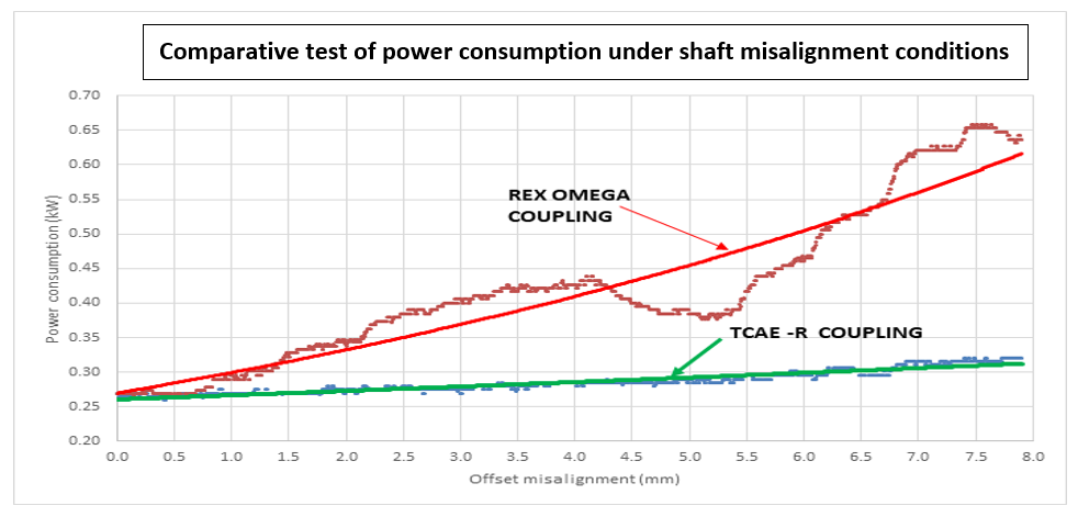
When the results were converted to an energy loss percentage within the normal range of allowable alignment for the Omega coupling the energy loss was apparent. Moreover at a relatively minimal offset of 0.9mm (0.035”) for this type of coupling losses of 10% energy can be observed.
The results are not unique and have been previously replicated by others including JC Lambley formerly of ICI Chemicals as shown below:
The TCAE coupling provides significant cost advantages in terms of energy savings and total cost of ownership through reduced power consumption, elimination of shaft alignments services, reduced wear on connected bearings and seals etc.
Production savings explained with TCAE ™ shaft couplings.
To demonstrate the effectiveness of the TCAE coupling in operation a number of case studies are presented from the company’s wide customer base. The following table shows just some of the many individual applications that the TCAE coupling has helped to solve compared to other traditional shaft couplings:
SEE NEXT PAGE FOR EXAMPLES
(Presented by David Farrell (B.E. Mech (Hons)) – Chief Engineer, Thompson Couplings Ltd.)
| Type and company location | Application | Power/Speed conditions | Existing Problem | TCAE Solution |
| Gold Mining dump truck PTO drive – Indonesia | Coupling required at diesel engine Power take off to drive hydraulic pump | 100kW, 2300rpm max diesel drive | Restricted engine compartment room meant direct coupling of the pump within standard coupling angular tolerances was not possible | TCAE-R-2 was installed with a shaft angle of 5 degrees allowing the pump to be situated unobstructed. The constant velocity nature of the coupling meant the pump operation remained smooth with no induced vibration from the coupling. |
| Water pumps for a large pulp and paper making plant – Sydney, Australia | Couplings required to operate in various sized water and slurry pumps | Various sized ranging from 11 kW, 1440rpm to 110kW, 1440rpm | Corrosive nature of the plant room has caused the concrete plinths used to mount the motor-pump bases to crumble. Significant downtime results from the requirement to constantly laser align the existing couplings under these “soft-foot” conditions | Various sized TCAE-R series couplings have now replaced the many existing pump couplings and have operated for many years without the need for any alignment. Furthermore the life of the pump seals has increased due to elimination of damaging side loads on the shafts from misalignment |
| Paper roll winder drives for a large paper making plant – Indonesia | Coupling connects DC motor to roll winder | 180kW, 920 rpm | The existing gear coupling of the paper winder shaft required continual re-alignment due to the shock loads imposed under controlled deceleration and stopping | TCAE-R-7 was installed with an integral disc brake to control the deceleration and emergency stopping of the paper roll. |
| Suction press pump driveshafts for a large paper making plant – Indonesia | Long driveshaft (3 mtrs) connects motor to pump | 185kW, 2100 rpm | Existing gear coupling regularly fails due to misalignment conditions | A Long series TCAE-L-7 installed to connect the motor gearbox to the suction pump |
| Roughing mill runout table driveshafts for a large steel plant – UK | Long bank of conveyor drive rolls feed hot steel slab through roughing mill | 85kW, 579 rpm | Current cardan universal driveshafts produce continual torsional vibration affecting slab quality. Also couplings fail prematurely due to reversing nature of drive | A customised TCAE-V-7 was installed with standard DIN flanges to mount to the existing shaft flanges. The constant velocity nature produces relative vibration free motion to the conveyor |
| Roller/Straightener driveshafts for a large steel rolling mill – Italy | Steel coil straightening machine with individual driving rollers | 2,5kW 120 rpm | Existing special gear couplings fail regularly and require constant oil feed lubrication due to speed and angle | A customised high angle version of the TCHA-SD-8 coupling driveshaft was used to connect the gearbox output shafts to the individual spindle rollers at an angle up to 12 degs |
| Large, Vertical driveshaft for a high torque aviation test rig – Spain | Brand new test equipment being constructed by OEM | 5,000 kW, 230rpm to 500 rpm | Requirement for a true constant velocity driveshaft able to handle high torque load, axially compress/expand and articulate angularly while under load | A 3 metre long customised TCAE-V-14 driveshaft was designed and installed to connect a gearbox to provide true constant velocity to a rotor mast with a varying shaft angle up to 3,1 degrees. The vertical operation of the shaft required a customised thrust bearing arrangement to support the vertical load as well as high torque. |
| Large air compressor drive coupling for an aluminium plant – USA | Direct coupled motor to compressor drive | 2,250HP, 225 rpm | Existing Falk gear couplings are unable to handle the alignment conditions required in this specific installation | TCAE-S-11 couplings installed at close DBSE (220mm) |
| Dosing pump drive coupling for a large soft drink manufacturer – Ireland | Coupling connection to an axial pump | 37kW, 1440rpm and 5,5kW 1440rpm | Acidic environment causes the existing Omega elastomeric couplings to fail regularly | TCAE-V-0 and TCAE-V-1 couplings installed with Nitrile rubber boot |
| Trimmer/Chopper drive for a large aluminium coil processing line – USA | Drive coupling with high angle requirement within a process line | 300kW, 350rpm | Existing cv joints installed were unable to handle the continual articulating angle and speed without being destroyed prematurely | TCAE-V-9 couplings installed operating at 6 degree angle while running at 350rpm |
| Hot oil process pump in a large oil refinery – Netherlands | Hot oil process pump in part of the refinery operation | 45kW, 1460 rpm requiring ATEX approval | Centrifugal pump for hot oil at 280C regularly requires constant alignment due to thermal expansion of the pump | TCAE-R-2 with ATEX certification installed which has sufficient axial expansion and angular articulation to cope with the pump temperature |
| Large axial fan driveshaft for tempering furnace- Italy | Hot air blower driveshaft | 400kW, 990 rpm length 3mtrs, operating at 100degs C | Current gear flex couplings not able to handle the excessive angular misalignment when exposed to the hot air of the fan | TCAE-L-5 driveshaft installed to cope with the thermal expansion of the hot air without affecting performance |
| Coal Stacker reclaimer conveyor driveshaft for a large steelworks – Australia | Belt conveyor head drive roller connected to gearbox | 110kW, 94 rpm | Existing gear couplings are unable to handle continual misalignment due to flexure in the stacker structure and are regularly failing | Customised TCAE-L-10 driveshaft with 2 piece shaft passing through conveyor boom. Each shaft requires angular misalignment capability due to flex in structure |
TECHNICAL UPDATE – “TCAE COST BENEFIT ANALYSIS AND RECOMMENDATIONS”
INTRODUCTION:
The object of this report is to research the current market data regarding power efficiency and losses associated with pump to motor couplings in particular and assess how much improvement can be gained from the TCAE as a selling feature.
PRODUCTS OVERVIEW:
Thompson Coupling Alignment Eliminator (TCAE):
The major characteristics of the TCAE are the large parallel (up to 17mm), angular (up to 5° per coupling unit) and axial misalignment (up to ±15mm) created by both joints avoiding side load on pump / motor bearings. The main component that drives the AE product features and selling prices is the CV joint and the whole product is based on that part. The product range of 5 different series totaling 92 couplings can accommodate motor sizes from 1KW to 400 KW with no required maintenance for the life of the coupling.
COSTINGS AND POTENTIAL SAVINGS:
There are 4 distinct potential cost savings that are considered in analysing the present use of shaft couplings commonly used in pump/gearbox to motor arrangements. These are:
- Initial capital purchase cost of the coupling
- Overall efficiency losses through the coupling due to misalignment
- Plant downtime due to replacement of motors, pumps and couplings as well as premature pump bearing and seal failures
- Preventative maintenance cost of periodic laser alignment services for the shaft couplings.
While it is currently understood that the TCAE coupling maybe slightly higher in initial capital outlay compared to existing gear/grid/elastomeric type couplings the latter 3 savings do provide a more compelling case for plant wide cost savings by switching to the TCAE coupling.
1. Efficiency savings:
An extensive literature review of the efficiency losses associated with shaft misalignment has been conducted. There have been many independent and university research studies conducted on this subject since the late 1960’s and mostly show there are significant losses with coupling misalignment – especially if the alignment falls outside the manufacturer’s specifications. Often with grid/ gear and similar couplings the allowable tolerances are quite tight (less than 1 mm offset and 1 degree angular). A recent industry report by the laser alignment advocates showed that more than 90% of machines have shaft misalignment outside their manufacturer’s tolerances.
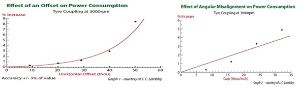
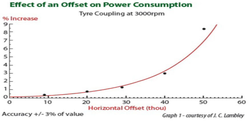
The most significant study by JC Lambley (known as the Runcorn study by ICI Chemicals) showed the effect of shaft misalignment on power consumption as follows: Note the offset distances are in thousandths of an inch. (10 thou= 0.25mm and 40 thou = 1mm)
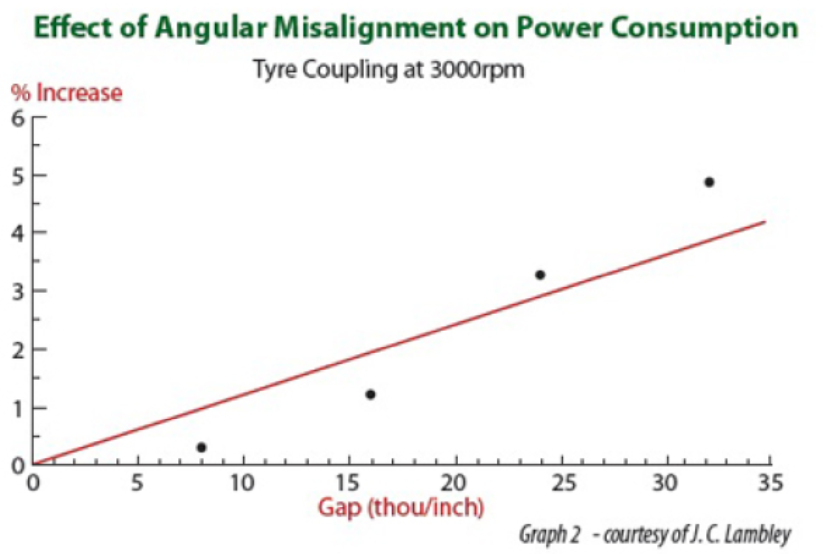
The same author produced the following graph for angular misalignment: Note the angles are in thou/inch (10 thou/inch = 0.5 degs)

This trend is similarly repeated by other authors with some citing savings between 3% and 10% and 9% being common in old plants in some situations.
Other authors quote very conservative efficiency losses of 1% to 1.5 %
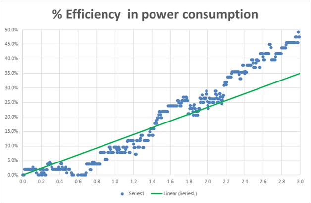
We conducted our own series of test experiments to try and determine the power draw of various couplings. In the following experiment we connected a 3 phase, 0.75 kW electric motor to a generator via a flexible tyre coupling (Omega) and then a TCAE (AE2) coupling. A series of power measurements was recorded after adjusting the offset gap by 0.1 mm increments. The results did show a significant difference in power consumption as follows:
When this is converted to an efficiency difference for just the first 1.6mm offset distance the following graph shows the result:
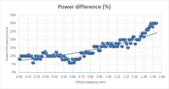
Clearly it can be seen that a 10% efficiency gain can be made with the TCAE with just a 0.5mm shaft offset.
But in summary the best realistic efficiency improvement that I have found using the TCAE – is 2.3%, and this after proper laser aligning.
“A ReliabilityWeb.com article, “Shaft Alignment, Soft Foot & Energy Savings,” cited studies that show you can get a real energy savings of 2.3% by aligning a loaded machine—and as much as 9% on an unloaded machine. For a plant spending $50,000 per month on energy, that would equal a savings of
$1,250-$4,500/month—or $15,000-$54,000 per year.”
Even if there is only 1% savings is that significant. (Michael Keohan 04/20/2012 Energy savings, Vigralign Blog) gave the following example.1% drop on a 480 volt motor running 8400 hours/yr drawing 50 amps (~40hp) with a cost of
$0.07/kWhr
kW Reduction = (480V)(0.5A)(0.92PF)(1.732)/1000
0.38 kW reduction
Total Savings = 8400 hours/yr x 0.38kW drop x $0.07/kWhr = $225 for this one machine Total Plant
savings for 50 machines, averaging 50A, if 50% are misaligned
$5625/yr
This is significant to any Engineer trying to keep operating costs to a minimum.
2. Reduced Downtime Savings
The potential cost savings in reducing downtime from a failed pump seal or motor bearing due to poor coupling misalignment can be enormous especially in a large plant with critical equipment.
There are 2 main type of equipment in a plants operation:
- Critical service equipment
- Non critical items
When considering critical service equipment, a much higher downtime cost would be attributable. This could be anything upwards of $10,000 per hour in some factories where the upstream and downstream processes are directly affected by the stoppage. Take a san example a large process pump that has a failed bearing due to poor coupling misalignment. The costs attributable to the failure maybe:
- Downtime to isolate the existing pump/gearbox;
- Downtime to fetch the new pump/gearbox from stores;
- Downtime to remove and install the new pump;
- Downtime to re-align the new coupling;
- Downtime to re-energise the pump/gearbox and bring back online.
This total downtime, being conservative, would take 1 hour to complete and if the rest of the process is directly affected is easily a $10,000 direct loss to production.
A Non-Critical item would be a similar pump which is coupled to a standby pump that fulfills the same function as the main duty pump. In this scenario if the main pump fails due to a similar fault as previous the downtime is much reduced due to a simple standby switching arrangement. In such situations care needs to be taken to understand the nature of the business for the intended installation of a TCAE coupling and its proposed cost benefit. The benefits here would be the removal, repair and reinstallation costs of the pump/gearbox, both in cost of parts or new machine and the labour costs involved. All this is drastically reduced using a TCAE coupling.
Other savings are possible with quantifiable costs for reduced bearing life in pumps, gearboxes and motors that are subjected to shaft misalignment conditions.
A published paper has estimated the following:
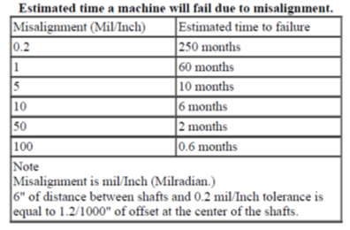
This can be converted to the following quick rules of thumb for convenience:
If the bearing load on a pump or motor is increased due to mechanical stresses by misalignment it will reduce the bearing life by a factor to the 3rd power.
Or
10% increase in bearing load = 24.9% of bearing life reduction in normal load.
20% increase in bearing load = 42.2% of bearing life reduction in normal load.
50% increase in bearing load = 70.4% of bearing life reduction in normal load.
3. Elimination of Laser Alignment service costs
As many companies realise the benefits of preventative and now predictive maintenance regime, they include a periodic check of the shaft alignments to ensure all is within the desired tolerances.
The last major cost to be identified is the actual cost to perform the continual laser alignment service on the many pumps and motors in a factory. These are often outsourced to specialist companies (such as SKF, Vibralign, PdM Solutions, Easy Laser etc) who charge for an inspection normally 3 or 4 times per year. The operation involves stopping the desired pump/gearbox/motor for a time while the necessary measurements and adjustments are made to bring the alignment back into specification.
In an ideal situation this may take as little as 20 minutes to perform before the pump is returned to service. BUT more often the pump or motor may have SOFT FOOT issues meaning the connected baseplate is not rigid. When this occurs, a technician can spend more time (often hours) to try and correct for poor shaft alignment only to be chasing his tail since the foundations are loose and cannot hold the required tolerances.
In both situations the pump is out of action for a period of time thereby causing loss of production. Added with the service technicians cost (maybe $100 – $150 per hour) equates to an expensive but necessary exercise in maintaining precise shaft alignment.
Enter the TCAE solution:
- No need to maintain the necessary shaft alignment tolerances as with conventional couplings
- Hence no need to employ service technician companies to perform laser alignments
- Hence no need to shut the pump down while such services would be undertaken
- Hence direct cost savings to the company.
- Also reduced forces on the shafts from misalignment means an increased service life of the pump and motor bearings as well as pump seals
- Furthermore a direct saving in production downtime is achieved with reduced problems in pumps and motors
- Finally a direct power efficiency of 3% minimal is achievable by switching to the TCAE due to reduced shaft loads from misalignment
References can be supplied to all studies if interested:
David Farrell B.E. Mech (hons). – Engineering Dept. Thompson Couplings Ltd.
TECHNICAL UPDATE – “Elevating Industrial Efficiency: Unveiling the Strategic Impact of Total Cost of Ownership in Coupling Selection”
While cheaper couplings may boast a lower initial cost, their true impact on maintenance, downtime, and potential production losses is underestimated. A more astute approach involves considering couplings engineered for durability and low maintenance, despite a slightly higher upfront investment. The enduring economic advantages of such couplings become evident over time.
Central to the TCO framework are maintenance costs. Cheaper alternatives, lacking the robustness of their pricier counterparts, result in frequent breakdowns, heightened maintenance needs, and increased operational costs. In contrast, premium couplings, designed for longevity, demand less frequent maintenance, ultimately trimming overall operational expenses.
Downtime emerges as a pivotal factor influencing production efficiency. Cheaper couplings fail unexpectedly, causing unplanned downtime and disrupting production schedules. Investing in high-quality couplings, renowned for reliability and extended service life, can significantly curtail unplanned downtime, ensuring continuous and uninterrupted production.
Moreover, the lifespan of couplings directly impacts replacement frequency. Cheaper alternatives wear out swiftly, necessitating frequent replacements and incurring additional costs. Thompson Couplings’ high-quality couplings, with their extended lifespan, reduce replacement frequency, translating into substantial long-term cost savings.
At Thompson Couplings, our steadfast belief is that the primary consideration when selecting couplings should be their ability to deliver maximum production gains. Opting for couplings that offer superior durability, ease of installation, and minimal to no maintenance aligns with our commitment to providing solutions that elevate efficiency and contribute to significant long-term cost savings and increased income.
By prioritizing TCO over initial costs, businesses can ensure a seamless and productive operational environment. Thompson Couplings encourages businesses to consider TCO when selecting couplings, emphasizing that investing in durable, high-quality couplings leads to minimized maintenance costs, reduced downtime, and enhanced overall operational efficiency. While the upfront cost may be slightly higher, the long-term savings, increased production, and improved reliability make premium couplings a wise and cost-effective choice for businesses committed to optimising their industrial operations.
In conclusion, businesses are urged to prioritise TCO considerations when selecting couplings for machinery. By investing in durable, high-quality couplings, companies can unlock the potential for minimized maintenance costs, reduced downtime, and heightened operational efficiency. Reach out to your local distributor or reply to this email to connect with your local branch and explore how Thompson Couplings can be the strategic coupling choice once your TCO is meticulously calculated.
TECHNICAL UPDATE – “OFFSHORE DRILLING RIG COUPLING”
Recognising the unique demands of the offshore drilling environment, we recommended one of our advanced series of couplings that excel in reliability, require minimal maintenance, and offer superior energy efficiency. By implementing our couplings on the offshore drill rig, we addressed the specific challenges posed by the moving platform and ensuring long-lasting, trouble-free operation even in the most challenging offshore conditions. Embracing these above attributes becomes imperative when every moment of downtime translates to financial losses.
We at Thompson Coupling chose the following coupling to fulfill the job requirements.
TCAE-S-8 coupling.
Operating angle – adjustable 0 to 10 degrees rotating.
Drill head power – hydraulic motor 90kW.
Drill shaft operating speed: up to 950 rpm.
Weight of drill rod assembly to be supported: 2 tonnes.
The maintenance-free nature of our couplings will play a crucial role in reducing downtime and operational disruptions on the rig. With a robust design, our couplings will prove to be a reliable and hassle-free solution, eliminating the need for frequent maintenance and repairs in the demanding offshore drilling setting.
Furthermore, the energy efficiency of our couplings contributes to cost savings and optimised performance on the offshore drill rig. By minimising energy consumption and maximising power transmission efficiency, our couplings will help streamline operations and enhance overall productivity, even in the face of constant motion and challenging environmental factors.
In conclusion, the integration of Thompson Coupling’s maintenance-free, energy- efficient, long-lasting couplings with up to 10 degrees of articulating misalignment on the offshore drill rig will not only resolve the previous issues with premature coupling failures but also demonstrate the adaptability and reliability of our solutions in extreme offshore conditions.
Imagine the remarkable capabilities of our state-of-the-art coupling system conquering wind, currents, and tide. Now picture the transformative impact it could have on optimizing your industrial operations and maximizing your financial efficiency.
Contact us or our distributor today, to learn more about how our advanced couplings can enhance the performance and efficiency of your industrial applications, even in the most demanding environments.
TECHNICAL UPDATE – “CUSTOM ENGINEERING DESIGN AND MANUFACTURE”
We are delighted to bring to your attention an aspect of Thompson Couplings that you may not be fully aware of. While we are renowned for our exceptional line of couplings, we want to emphasise that we have been offering bespoke engineering design and manufacturing services for a long time.
At Thompson Couplings, we pride ourselves on our commitment to providing tailored solutions to meet your specific requirements. Whether it’s solving complex challenges or optimising efficiency, our expert engineers have always been here to support your needs.
Here are just a few examples of how our engineering design and manufacturing expertise combined with our reliable couplings have made a difference:
Water Supply Vertical Application: We designed a coupling with a 2.5-metre shaft featuring a 10-degree swing. This innovative solution not only meets the specific needs of the application but also integrates seamlessly with our standard couplings, ensuring long-term reliability and ease of maintenance.
Helicopter Test Bed Couplings: Our precision-engineered couplings provide seamless power transmission from the motor to the blades and from the motor to the tail rotor, minimising vibration and reducing the need for frequent maintenance checks.
Offshore Drilling Rig Coupling Solution: Our standard couplings, known for their durability and reliability, were the perfect fit for solving a challenging coupling issue at the top of a drilling shaft on an offshore rig. Their long life and low maintenance requirements ensured uninterrupted operations in a demanding offshore environment.
Mining Truck Power Take-off Unit: Designed specifically to handle four degrees of misalignment, our custom power take-off unit for a mining truck showcases the adaptability and reliability of our standard couplings.
These examples demonstrate not only our commitment to delivering custom engineering excellence but also the reliability and durability of our standard couplings. Whether it’s a custom solution or a standard coupling, Thompson Couplings is your trusted partner for engineering solutions that last.
In addition to our unique engineering solutions, we want to highlight the outstanding features of our standard couplings. Our entire range of couplings is engineered to reduce maintenance needs, making them hassle-free and cost-effective. They are designed to be easy to fit, saving you time and resources during installation. Furthermore, our couplings boast a long lifespan, ensuring reliable performance throughout their service life.
Our existing range of couplings includes solutions for a wide range of applications, from standard to highly specialised needs. These couplings are meticulously designed to meet the highest standards of reliability, durability, and ease of maintenance. Whether you require couplings for industrial pumps, automotive applications, or marine systems, Thompson Couplings has you covered. The best part of all is that using one of our Couplings will reduce your maintenance costs and increase your productivity.
We invite you to explore the full range of possibilities with Thompson Couplings and experience the difference our engineering expertise and reliable couplings can make in your projects. Contact your distributor or Thompson Couplings directly today to discuss your specific requirements and let us help you save money and time.